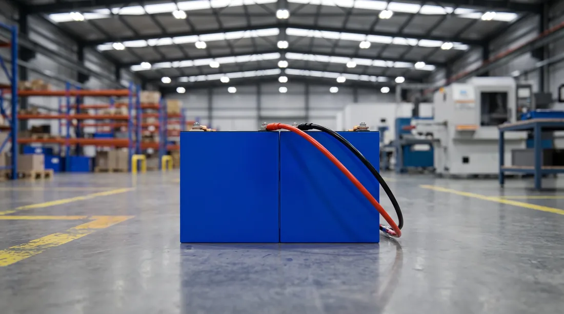
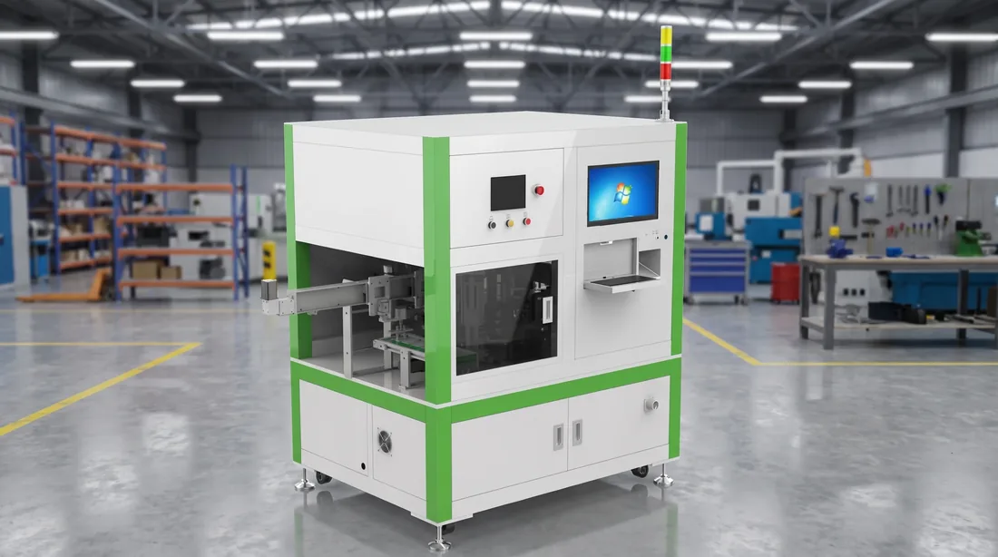
Busbar laser welding / BLP-W6 — module segment, station 13 of 17
Four Figures Are Published for a Busbar Weld. Only Two of Them Are Criteria.
6 kW, 50 to 100 mm/s, fusion at least 1.0 mm deep and 1.5 mm wide, and a joint that holds 1000 N. This page says which of those your inspector can hold us to, and how.
⚠️ A pull test destroys the joint it proves. What a line running at takt does about that is section 06 — and it is the reason this page exists.
What this station promises
- Told where the joint is — it does not go looking for it
- Welded in line, at line takt — the module never leaves its carrier
- Proved by a test that consumes the joint — so sampling is written, not assumed
- 6 kWLaser source
- 50–100 mm/sWeld speed
- ≥1.0 mmFusion depth
- ≥1000 NJoint pull strength
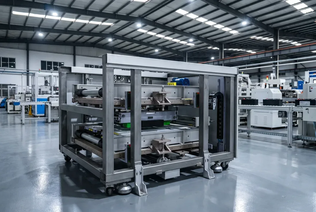
Station thirteen of seventeen, and it inherits almost everything
A busbar welder is bought as a machine and lives as a station. What arrives at it has already been decided by three stations upstream, and the welder cannot argue with any of them.
Module segment · station 13 of 17 — busbar laser welding
- 11Terminal addressing and laser cleaning
- 12CCS and busbar plate fitting
- 13Busbar laser welding — this stationYou are here
- 14Post-weld cleaning and inspection
- 16Module end-of-line test
A weld you can see and a weld that holds are separated by one millimetre of metal nobody can look at.
Depth
Width
Strength
The four figures we publish, and what each is a criterion for
⚠️ Two of them describe the machine and two describe the joint. Reading a machine figure as a quality figure is the commonest way a welding quotation gets oversold.
| Figure | What it is a criterion for |
|---|---|
| 6 kWLaser source | Nothing about your joints. It is capability, and its value to you is the margin left over when your busbar is thicker or your material more reflective than the blueprint one. Section 11 → |
| 50–100 mm/sWeld speed | A window, not a setpoint. Where inside it your joint runs is settled with your busbar material and section, and a supplier who names one number before seeing them has named it for somebody else's module. Section 07 → |
| ≥1.0 mm / ≥1.5 mmFusion depth and width | The per-joint criterion. This is the pair an inspection procedure is written against, because it can be checked on the joints that stay in the module. Section 07 → |
| ≥1000 NJoint pull strength | The joint criterion buyers trust most and can afford least often — the measurement destroys the joint it measures. Section 06 → |
≥1000 N is the figure buyers trust and the one you cannot re-check
This is the part of a welding specification that decides how the station gets accepted, so it gets the long answer instead of a table row. Everything else on this page follows from it.
- 01 · Why this figure
A pull figure is the only published number that describes the joint doing its job
Depth and width describe the shape of the fusion zone; ≥1000 N describes what happens when somebody loads the busbar. That is why it is the first number an engineering department asks for, and the last one a brochure explains. - 02 · What it costs to obtain
The joint is gone once you know the answer
A pull test loads the busbar until the joint gives up. The joint is destroyed whether it passes or fails, and the module it belonged to does not go back on the line. 100% pull testing is not an inspection plan; it is a scrapping plan — which is exactly why it has to be designed rather than promised. - 03 · What runs at takt
The station holds the conditions under which 1000 N was proved
Per joint, in line, what is controlled is the parameter set and what is checked is the fusion geometry — ≥1.0 mm deep, ≥1.5 mm wide. Strength is established on samples against your busbar and your terminal, and the line's job from then on is not to drift away from the state that produced it. - 04 · Why the three are one argument
Geometry is the daily evidence, strength is the periodic proof
Read separately they look like three claims. Read together they are one method: prove strength on a sample, lock the parameters that produced it, and verify per joint that the fusion still has the shape those parameters make. - 05 · When a sample fails
A failed pull sample is a parameter question, not a re-weld question
The honest response is to bracket back to the last passing sample, quarantine what ran in between, and find what moved — fixture, material lot, surface condition. Re-welding a joint that already has fusion under it does not repair the joint; it adds heat to a module you have not yet diagnosed.
Why an under-made busbar joint is dangerous rather than merely weak is argued once, on the equipment page, and is not repeated here.
Take this to any supplier
"How is your joint-strength figure obtained, on how many joints, and what happens to the module each of those joints came from?"
› — What that answer has to contain
- The sample basis — which joints, on whose parts, at what settings
- Who agrees the frequency, and when it is written down
- What is checked per joint instead, and against which figure
- Where the destroyed sample goes on the day it fails
The pull test is a bench operation beside the line, not a station on it
Depth and width are one criterion written as two numbers
≥1.0 mm and ≥1.5 mm are not two independent targets. They describe the same fusion zone from two directions, and a joint can miss the criterion by meeting only one.
| Geometry | What it rules out |
|---|---|
| ≥1.0 mmFusion depth | A joint that is wide on the surface and shallow underneath — the one that looks finished, passes a visual check, and carries current through a fraction of the section it appears to. |
| ≥1.5 mmFusion width | A joint that reached depth in a track too narrow to spread load — enough metal joined, in the wrong shape to hold the busbar when the pack is handled or vibrated. |
| 50–100 mm/sThe speed that produces both | Travelling too fast for depth or too slow for width. The window exists because the two requirements pull in opposite directions; where your joint sits inside it is set with your material, not before it. |
The station is told where the joint is. It does not search.
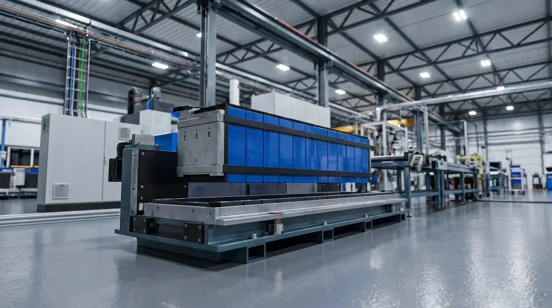
Every accuracy figure quoted anywhere on this line is quoted with respect to a datum. On this station the datum arrives with the module, and what that buys and costs is worth stating plainly.
- The module arrives located on its carrier, not placed by hand
- Terminal positions have been confirmed at the addressing station upstream
- The busbar plate and CCS are seated flat, not nearly flat
- Joint positions come off your module drawing, not off a sample module
- It does not correct a stack that was pressed out of square
- It does not compensate a busbar plate that is sitting proud
- It does not decide the joint layout — that is your module design
- It does not re-find a module that arrived approximately
This is not a disclaimer; it is the reason the numbers above are worth anything. A station that has to find the part again before it welds is a station whose repeatability figures describe its search, not its weld. Ours are quoted for a part that arrived where the station was told it would be — which is what conveying and positioning exists to deliver.
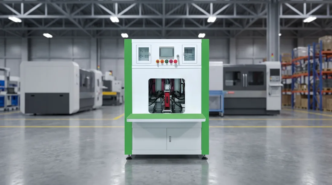
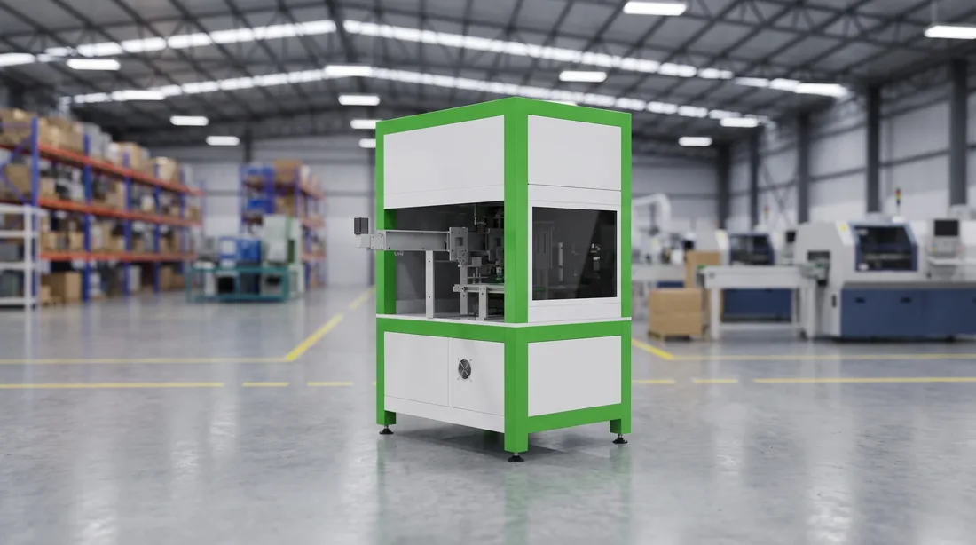
Send the busbar layout and one module drawing
Joint positions, busbar section and material, and whether your module is single-row or double-row. That is enough to say what this station would be quoted as, and whether you need it at all.
Reply within 24 hours / If hand welding is the honest answer for your volume, we will say so
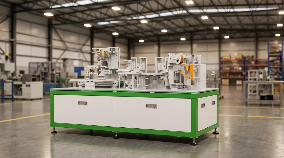
Single-row and double-row modules run on the same station
That is a published capability and it is worth reading precisely, because "universal" survives contact with a quotation only if somebody says which parts of the station change and which do not.
| What a row change moves | What it does not move |
|---|---|
| The joint map the station is given — how many joints, where they sit, in what order they are welded | The station itself: gantry, scanner and source are unchanged by row count |
| The fixture that presents the module, cut against your module envelope | The published criteria — ≥1.0 mm, ≥1.5 mm and ≥1000 N do not soften because there are two rows |
| Cycle content at this station, because the number of joints changed | Your takt, which is set by the slowest station in the segment rather than by this one |
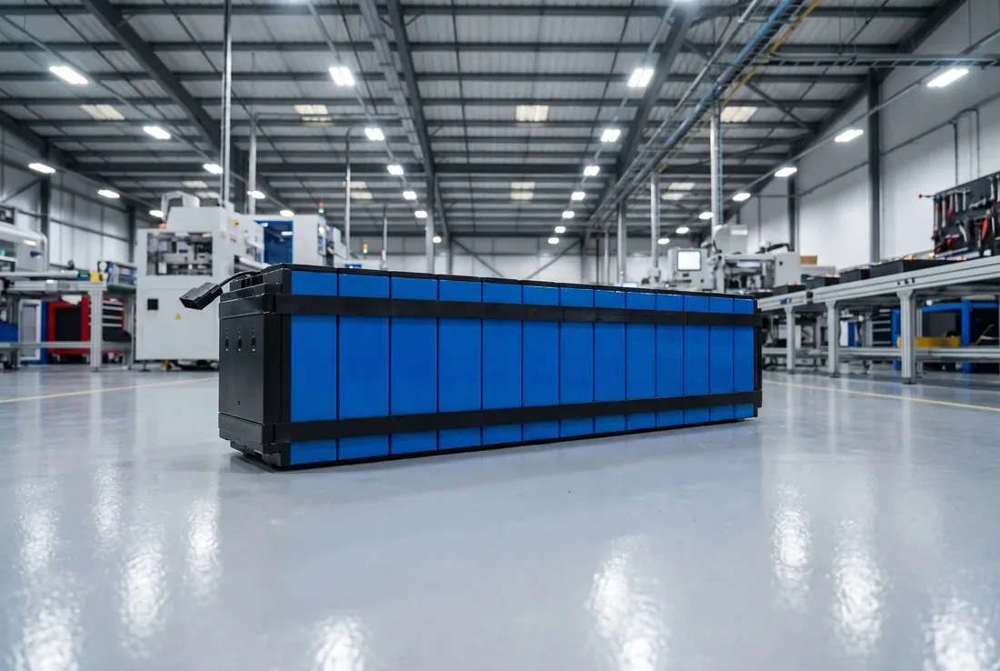
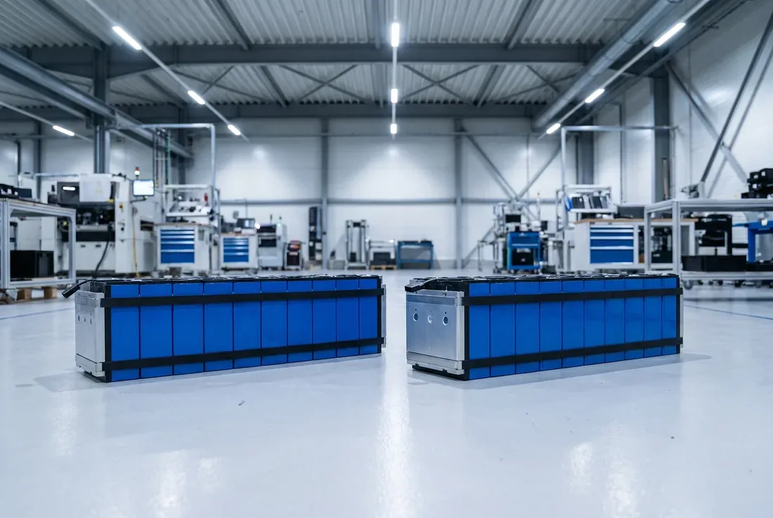
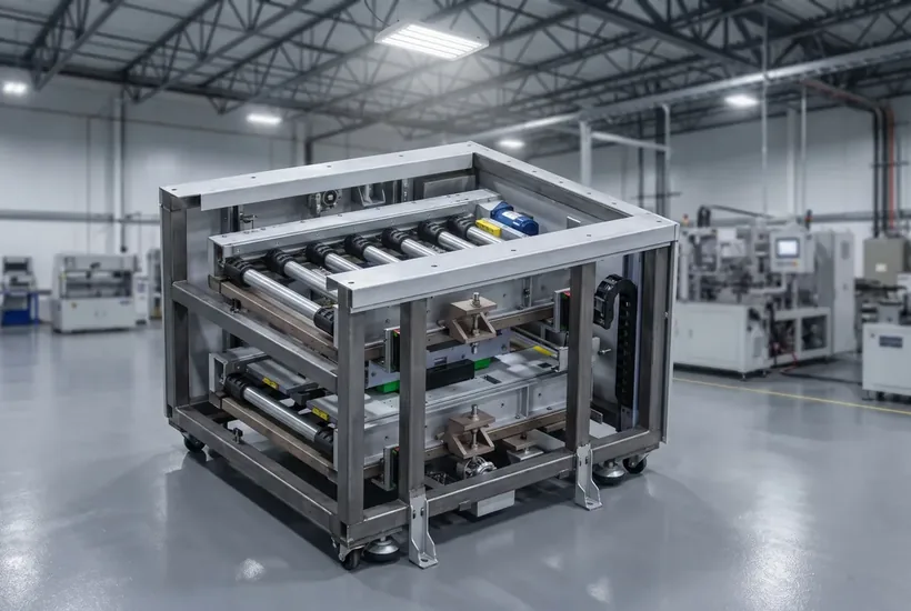
6 kW is headroom, and headroom is what a window is made of
The joints on a blueprint module do not need everything a 6 kW source can deliver. That is the point, and it is worth a paragraph rather than a bullet.
A rating is sized for the worst part you will ever run
Headroom is what lets speed stay a window
More power is not a better weld
Which is why the honest way to read a 6 kW line item is as an envelope, not an achievement. It tells you what the station can still do when your busbar turns out to be thicker than the one in the drawing — and that is a question every project eventually asks.
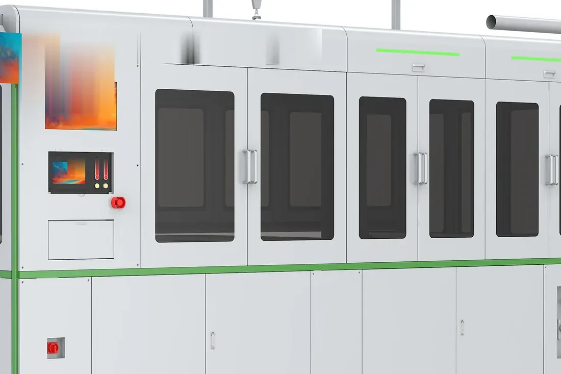
Four numbers you will want that this page leaves blank
Each blank has a different reason, and none of them is that we do not know. Writing them down is more useful than filling them with figures that would describe another customer's module.
Sampling frequency for the pull test
Joints per module
Cycle time for this station alone
A settings table by material and thickness
Four blanks with four different reasons is a specification; four blanks with one excuse is a brochure. Each of these is answerable — three of them with your drawing, and the fourth with your parts on our machine.
What is delivered besides the station itself
A welding station that arrives without the argument for its settings is a station your process engineer has to characterise again. These three things travel with ours.
The sample basis, in writing
The locked parameter set
Installation, commissioning and training
None of this is unusual, and that is the point: it is what separates a station you can accept from a machine you have to characterise yourself. Ask any supplier for these three and the answers will tell you more than the datasheet did.
Four questions that separate a welding station from a laser
None of them needs a drawing to ask, and all four can be put to any supplier — including us — before anything is committed.
| Ask this | What a real answer sounds like |
|---|---|
| Which of your published figures are acceptance criteria? | Two of them, and here is the document they go into. A supplier who says "all of them" has not thought about how the strength figure is obtained. |
| How is the strength figure proved, and how often? | On samples, at a frequency agreed with you, against your busbar. ⚠️ An answer of "every joint is tested" is either wrong or expensive beyond belief. |
| What does the station receive, and from where? | A located module and confirmed terminal positions. If the answer is that the machine finds the joints itself, ask what happens the day it finds the wrong one. |
| What changes when my module changes? | Fixture and joint map. If the answer includes the criteria, the criteria were never criteria. |
Our four answers are on this page: two of four; on samples against your parts at an agreed frequency; a located module with confirmed terminals; and fixture plus joint map, with the criteria unchanged. Everything above was written so those four can be checked rather than trusted.
Where the neighbouring stations and the thresholds are written up
This page owns busbar welding and its acceptance, and nothing else on the line.
- Module segment
- Busbar welding — you are here
- Pack segment
- Testing and acceptance
Send the busbar layout, and we will send back a scope
Joint positions, busbar material and section, row count, and the module drawing they belong to. Four inputs, and the station is specified from them rather than from a catalogue.
What comes back
If the answer is that you do not need this station