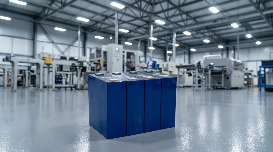
Module segment / seventeen stations, three levels
Battery Module Assembly Line,
Station by Station
Prismatic cells in at one end, welded and tested modules out the other — with every station marked AUTO, SEMI-AUTO or MANUAL before you sign anything.
Seventeen stations — station 09 is the only SEMI-AUTO position on the line, and station 13 is the one that cannot be undone.
The two stations that decide it
- Station 09 — the only SEMI-AUTO position
- Station 13 — the one that cannot be undone
- Station 16 — where the verdict is attached
By the time this segment is quoted, the module is already designed
Which means the line is not being asked what a module should be. It is being asked to build the one you already drew.
The cell is fixed
The module structure is fixed
What is still open is the sequence
That is the whole subject of this page
The pack segment is the other half of the same line and is written up separately, station by station. This page stops where a finished module leaves — what happens to it after that belongs to the pack segment page.
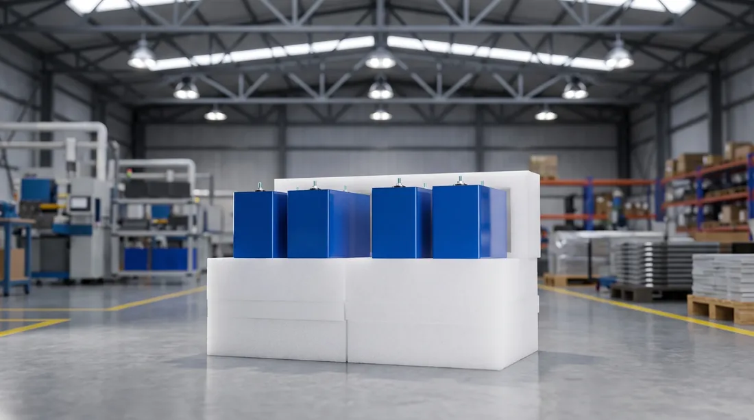
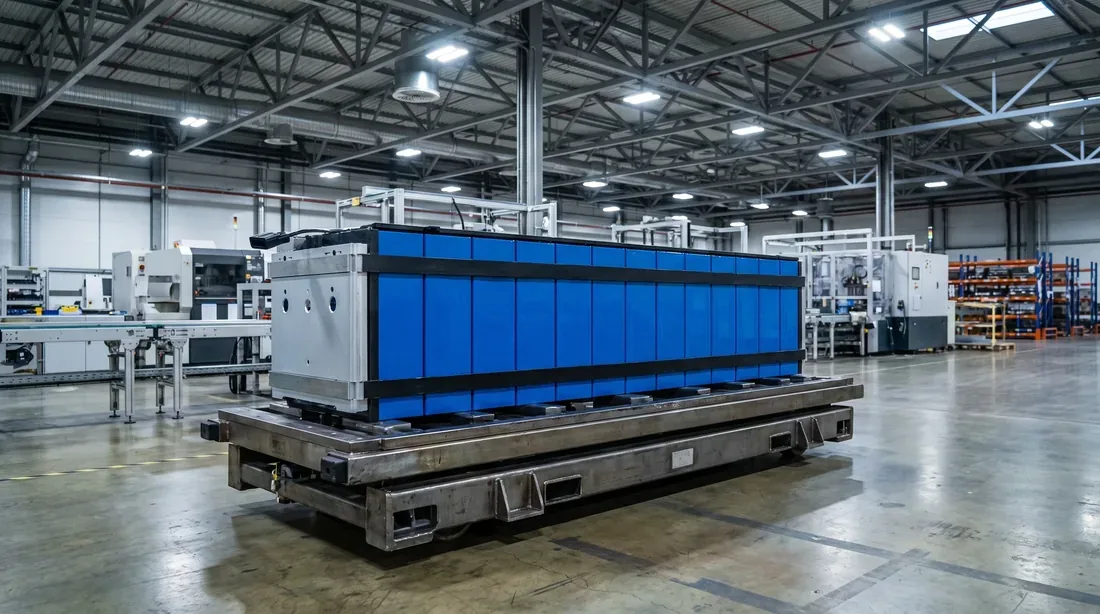
Three ways a module segment goes wrong, and the station where each one happens
None of them is exotic. All three are the same shape: something upstream was almost right.
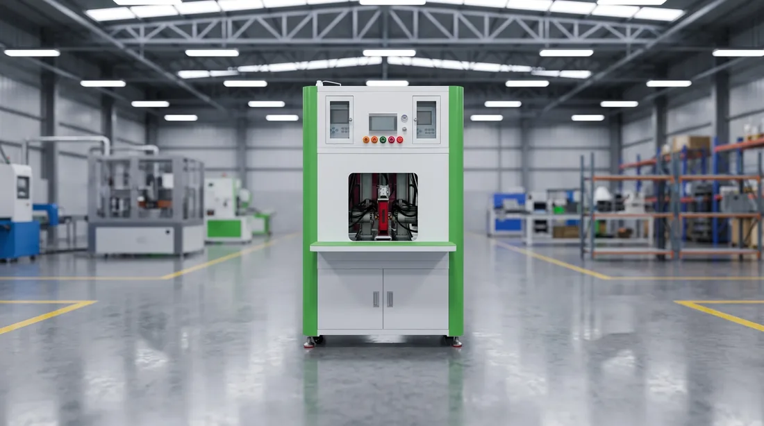
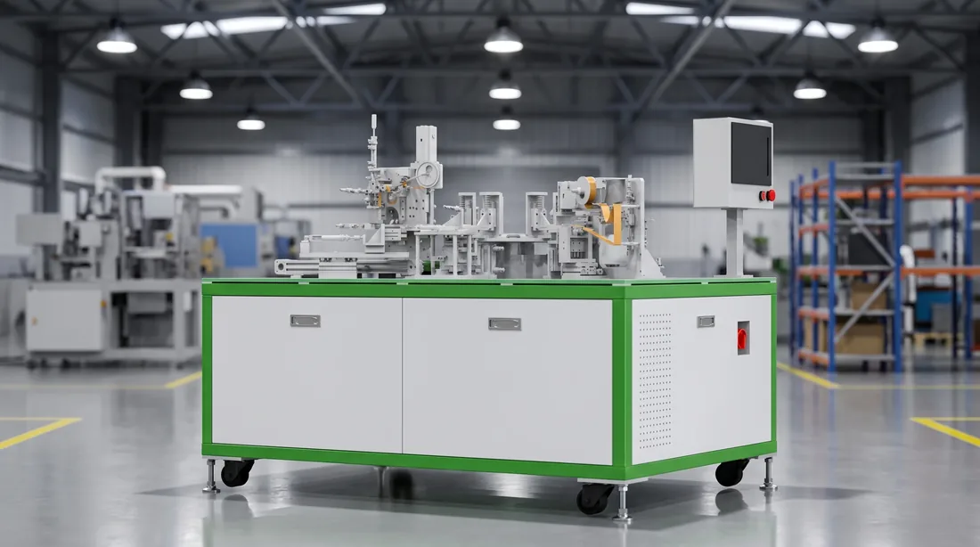
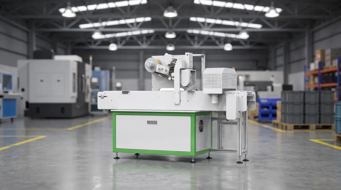
All three share a property that makes them expensive: the operation that reports the problem is never the operation that caused it. That is why this page names all seventeen positions rather than describing the segment as “automated”.
A module segment does not fail at the welder. It fails twelve operations earlier, and the welder is simply the first machine that cannot work around it.
Station 02
Station 09
Station 13
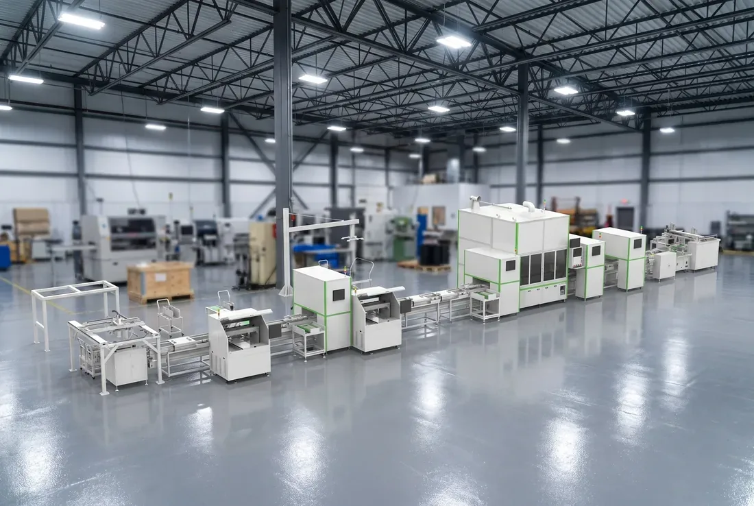
The module segment: seventeen stations, named
Levels describe the standard configuration. Cells arrive sorted; modules leave welded, tested and ready for the pack segment.
- 01Cell unloading and feedingAuto
- 02Cell scanning, OCV test and sortingAuto
- 03NG removal and OK refillAuto
- 04Cell flipping and groupingLevel set by tier
- 05Large-face plasma cleaningLevel set by tier
- 06Cell tapingLevel set by tier
- 07End plate and insulator handlingLevel set by tier
- 08Module stackingAuto
- 09Pressing, shaping and steel bandingSemi-auto
- 10Polarity and insulation testAuto
- 11Terminal addressing and laser cleaningAuto
- 12Busbar plate and CCS assembly installationLevel set by tier
- 13Busbar laser weldingAuto
- 14Post-weld cleaning and inspectionLevel set by tier
- 15Manual re-inspection and communication testManual
- 16Module end-of-line testAuto
- 17Module offloadLevel set by tier
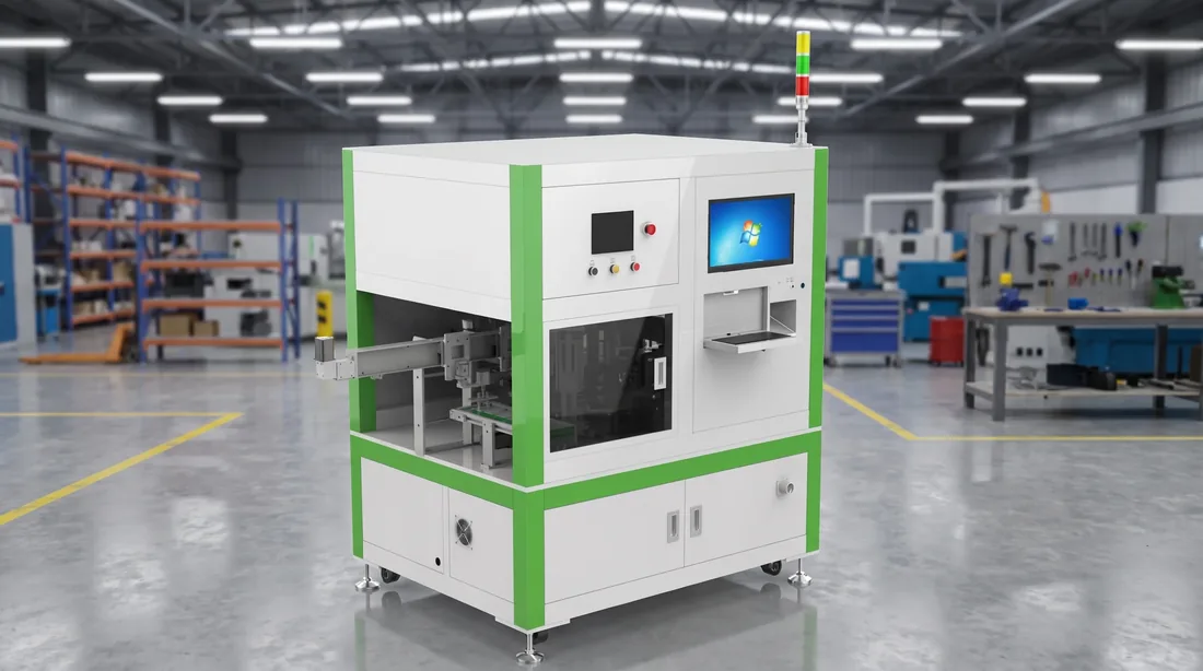
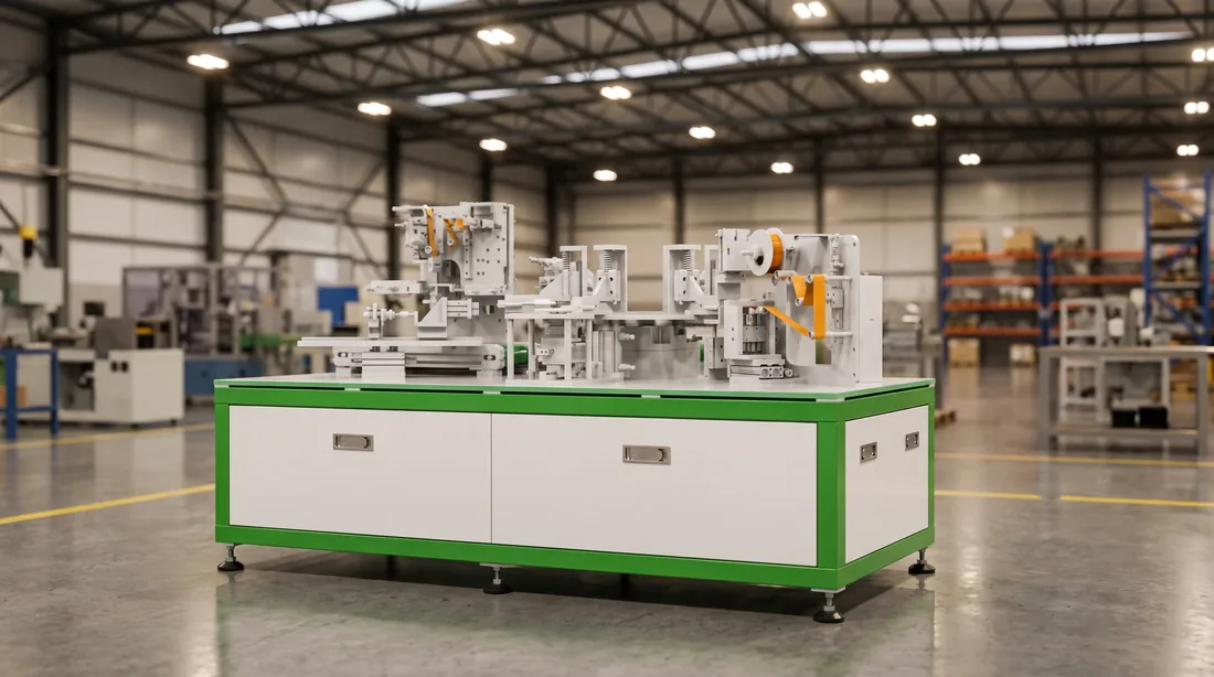
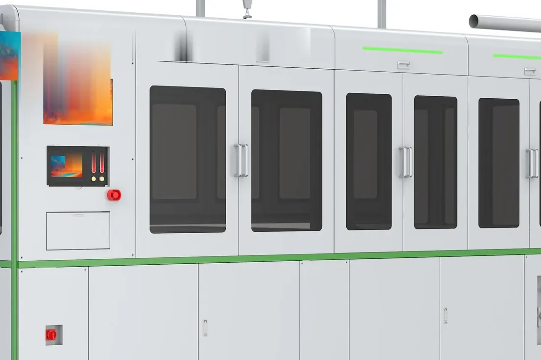
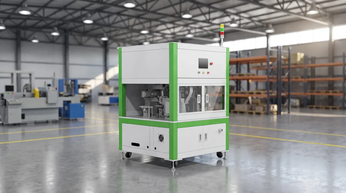
Seventeen stations, four things they are doing
Read as a list it is seventeen stations. Read as a sequence it is four moves, and only one of them is irreversible.
Prepare the cell
Build the stack
Join it
Prove it and hand it over
Prepare the cell · build the stack · join it · prove it and hand it over.
Nine stations before anything is joined
One phase you cannot re-enter
The proof is three stations, not one
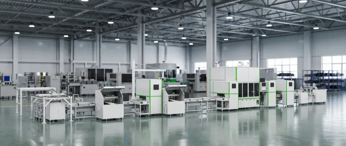
Three things must already be true before the welder is allowed to fire
The welding station is not where a module is made or lost. It is where the previous twelve stations get their answer.
- Why this one
Of the seventeen, this is the only station whose success is decided somewhere else.
The machine does what it is told, quickly and repeatably. What it is told comes from Station 11 (where the terminal is), Station 12 (what is seated on top of it) and Station 09 (whether the stack is still the length everyone assumed). - What has to be true
Three conditions, none of which the welder checks.
The terminal has to be where addressing said it was. The busbar plate and CCS have to be seated flat rather than nearly flat. The stack has to have stopped moving. Each is another station's output, and the welder inspects none of them — it welds where it was pointed. - What it costs when one is not
Not a bad weld you can see.
It is a joint with less contact than the drawing assumed, on a module that will pass its tests and then spend ten years carrying current through the one position that was never designed to behave like a fuse. By then the module is inside a pack, in somebody's installation. - What we do about it
The three conditions are stations, not assumptions.
Addressing and laser cleaning immediately before, CCS installation immediately before that, and the banded stack checked before the module ever reaches the joining phase. The weld runs in-line on a located part, not on a part that was placed. - What proves it
Figures on the page that owns them, with the acceptance method beside them.
Weld geometry and joint-strength criteria, and the method used to accept them, are published on the busbar welding station page — where they can be checked line by line against the quotation on your desk.
Weld geometry and joint-strength figures are stated once, on the busbar welding station page.
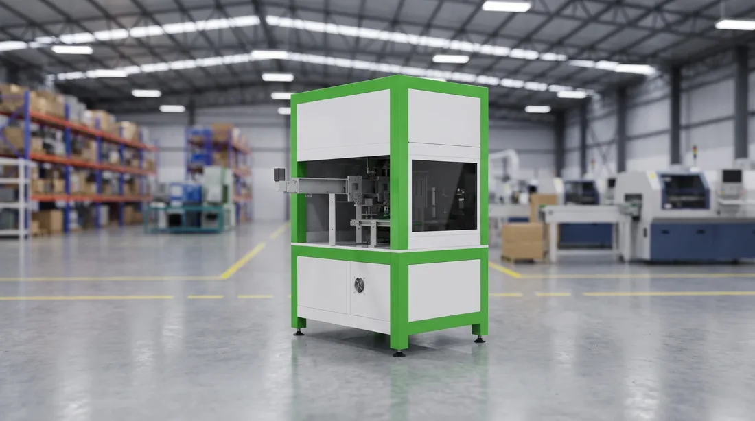
One station is neither automatic nor manual, and that is the honest answer
Pressing is the machine's job. Banding is not. A quotation that calls this station automated has rounded in the direction that flatters it.
AUTO
SEMI-AUTO
MANUAL
- Why this one
It is the only position in the segment that needs both.
Servo pressing gives the stack a dimension; steel banding is what makes that dimension survive the rest of the line. Calling the pair AUTO overstates it; calling the pair MANUAL hides the machine that does the hard part. - Rounded up to AUTO
Two errors, one shift.
Your headcount model loses a person who is actually standing there, and your takt model assumes a cycle nobody has to keep up with. Both show up at commissioning, together, on the same shift. - Rounded down to MANUAL
You budget and train for the wrong thing.
You budget hand-work at a position that is machine-paced, and you plan a training programme for a skill the operator does not need — while the skill they do need, keeping the banding consistent, gets no attention at all. - What we do about it
Three levels, published in three places.
The segment publishes three levels rather than two, and this station carries the middle one. AUTO, SEMI-AUTO and MANUAL appear on the layout drawing, in the station list, and in the acceptance document — and they agree in all three. - What proves it
A question you can ask before you order.
Ask any supplier which stations in the module segment are SEMI-AUTO. A segment quoted with only two levels has either never had one, or has stopped mentioning it.
The same module segment serves storage and EV customers
The sequence does not change between them. The module envelope does — and with it every fixture that touches it.
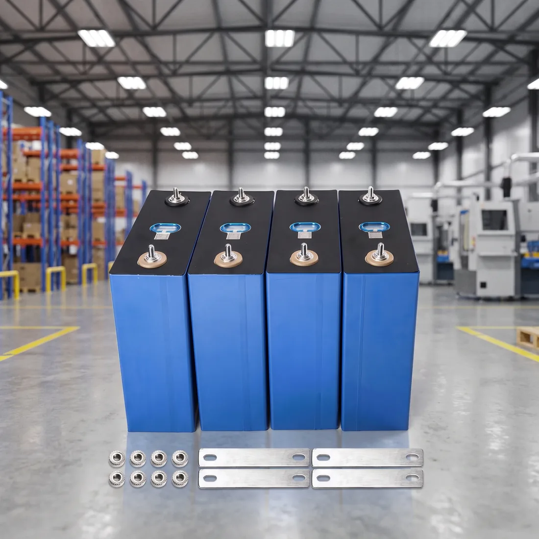
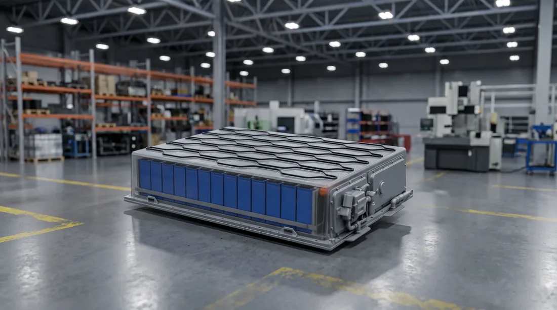
The sequence does not move
The tooling does
Station lists mislead across markets too
Your cell decides the first six stations; your module decides the next eleven
Which is why both drawings are asked for before anything is cut, and why neither can be substituted with a blueprint.
The cell sets the front of the segment
The module sets the back
1P13S is the blueprint we quote against
A segment quoted without those two drawings is a segment quoted against somebody else's module. It will be the right price for the wrong line, and the difference appears as tooling changes after the order rather than before it.
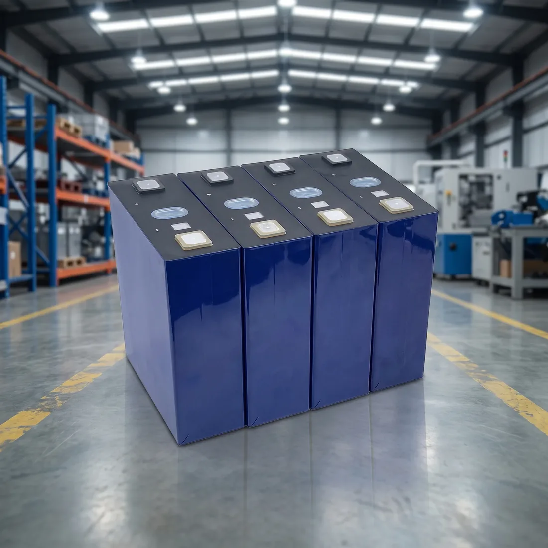
This is the half of the line where the machines are
Which is worth stating plainly, because the other half is not — and a single headcount figure for “the line” hides both.
BLP-P8S and BLP-P15 alike
- 4Module welding section, BLP-P8S
- 3Module welding section, BLP-P15
- 1SEMI-AUTO station in the segment
The higher-automation tier needs one fewer person in the welding section, not ten fewer — automation in this segment buys consistency and takt rather than an empty floor. The pack segment is staffed very differently, and its figure is published on the pack assembly line page rather than averaged into this one.
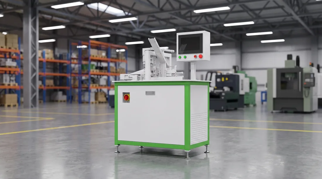
Send the cell drawing and the module drawing
Those two decide every fixture in this segment. With them we can come back with a station list, the levels against each station, and a layout drawn into your bay.
Reply within 24 hours / If the module is not designed yet, say so — that changes what is useful to send
What a module has to be when it leaves this segment
Four properties. All four are checkable, and all four are what the pack segment is entitled to assume.
- Property 01
Dimensioned
The banded stack is the length and width the pack enclosure was drawn for, not the length it was before banding. - Property 02
Joined
Busbars welded, post-weld cleaned and inspected, with nothing loose on top of the module. - Property 03
Proven
Polarity, insulation and communication checked, with a result attached to the module rather than to the shift. - Property 04
Located
Sitting on the carrier the pack side's receiving tooling expects.
The handover itself is a whole-line question
Module EOL thresholds are published separately
What a different module does to this segment
Less than people fear at the front of the segment, and more than they expect at the back.
The sequence survives
The front adapts cheaply
The back is where the cost is
What falls inside the compatibility envelope, and what a change costs in tooling and downtime, is set out on the compatibility page — with figures, which is why they are not repeated here.
Where the pack segment, the equipment and the figures are written up
- Cell handling
- Module segment — you are here
- Pack segment
- Offload
If the module is not final, say so before it is quoted
A segment quoted against a module that is still moving is a segment quoted twice.
The second quotation is the expensive one