Layout and utilities / what your building has to provide
Four Services, Three Configurations, and Not One of Them Is a Range
Clear height, floor loading, power, compressed air and nitrogen. Most supplier pages give you a range across all three line configurations. A range is exactly what hides the one you are buying.
⚠️ Pressure is common to all three configurations. Flow is not — compressed air runs 3000, 3500 or 5500 L/min depending on which line you buy, and the order of those three is not the one you would guess. Section 08.
Three things this page assumes
- Your building is the input — the layout is drawn to it, not the reverse
- The figures differ by configuration — and one of them runs backwards
- They have to be there before commissioning — not discovered during it
- ≥800 kg/m²Floor loading
- 380 V ±5%Three-phase five-wire, 50 Hz
- 0.5–0.7 MPaCompressed air
- 0.5 MPaNitrogen
Five building figures, and the reason they get answered last
Nobody signs a line because of its nitrogen consumption. That is precisely why these five arrive at the end of a project, when the only remaining way to fix them is expensive.
What is on this page
What is not on this page
Why the two are separate
The building question is the only one on the whole project that cannot be solved by changing the order. Everything else in a quotation is negotiable up to the day it ships.
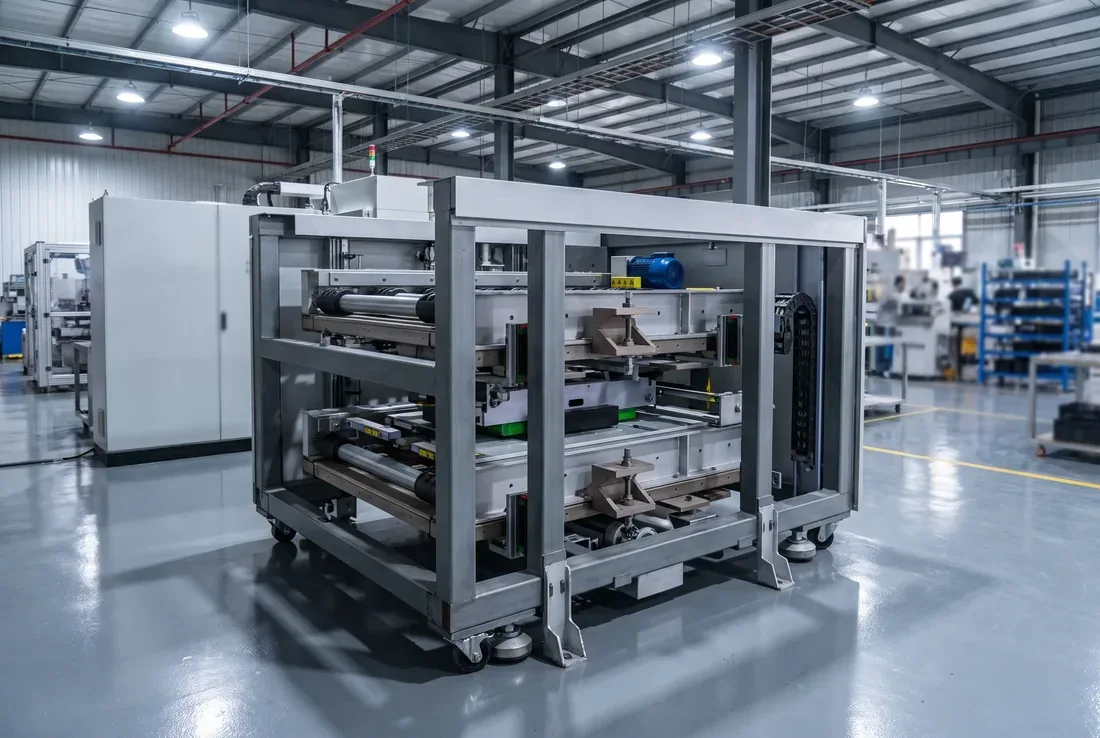
This page is about our lines, and the boundary is worth stating
Utility figures are only meaningful attached to specific equipment. These are ours — for the module and pack segments, and for nothing on either side of them.
What the figures describe
What they do not describe
What is yours to provide
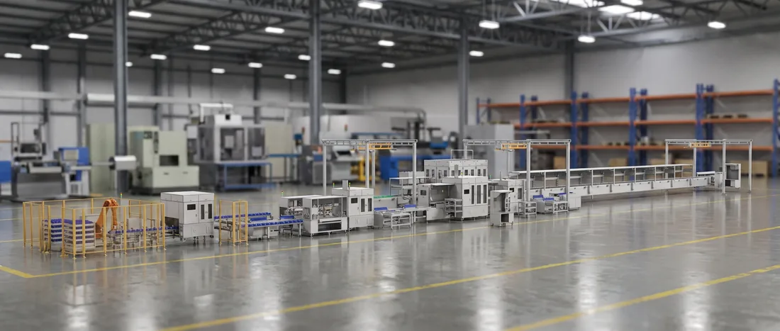
A line that will not fit is discovered on a drawing. A utility that will not reach is discovered on the day it is needed.
On a drawing
On the day
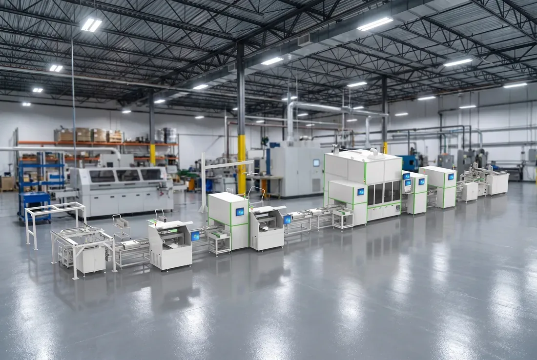
Between 3.5 and 4 metres of clear height, and clear means clear
The three configurations are 4, 3.5 and 4 metres tall. The number that matters is not the line's height — it is what is left underneath everything already hanging in your bay.
Measured to the lowest obstruction, not to the roof
The standard configuration is the lowest at 3.5 m
Above the line is not free space
Send the height to the lowest thing in the way, and the run of the bay it applies to. A single number for the building is the one most likely to have been measured to the roof.
≥800 kg/m², and what that figure is not
It is the figure most often answered from a building drawing without anybody checking which part of the building the drawing describes — and that is where it goes wrong.
- The slab under the run where the line actually stands
- Distributed load from frames, carriers and the parts on them
- The condition the line is commissioned against
- A figure both sides can check before anything ships
- Point loads under individual machine feet
- Mezzanines, pits, trenches and expansion joints crossing the run
- The route your machines take to get to that slab
- Anything above the slab — that is clear height
800 kg/m² is not a demanding figure for an industrial slab, and that is exactly why it gets waved through. The failures are never a slab that was too weak overall — they are a trench, a joint or a mezzanine crossing the one line of the building the run needs.
Take this to whoever owns your building
"Does the 800 kg/m² figure describe the bay where the line will stand, or the building average — and does anything cross that run below floor level?"
What to send instead of a single number
When it has to be settled
Three-phase five-wire, 380 V ±5%, at 50 Hz
Three properties in one line, and each is a separate question for whoever runs your electrical infrastructure. Two of the three are commonly answered by assumption.
Five-wire, not four
380 V ±5%, not "around 380"
50 Hz
How much of it
Take these three to the person who owns your distribution board, not to your project manager. The answer that matters is whether the board can present five wires at that tolerance where the line will stand — not whether the building has power.
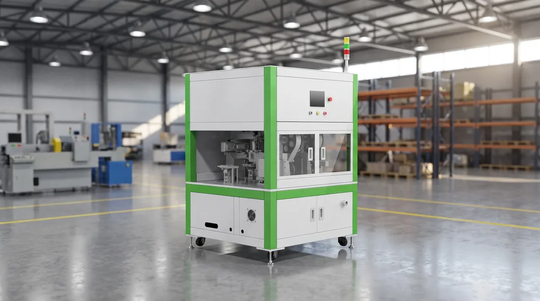
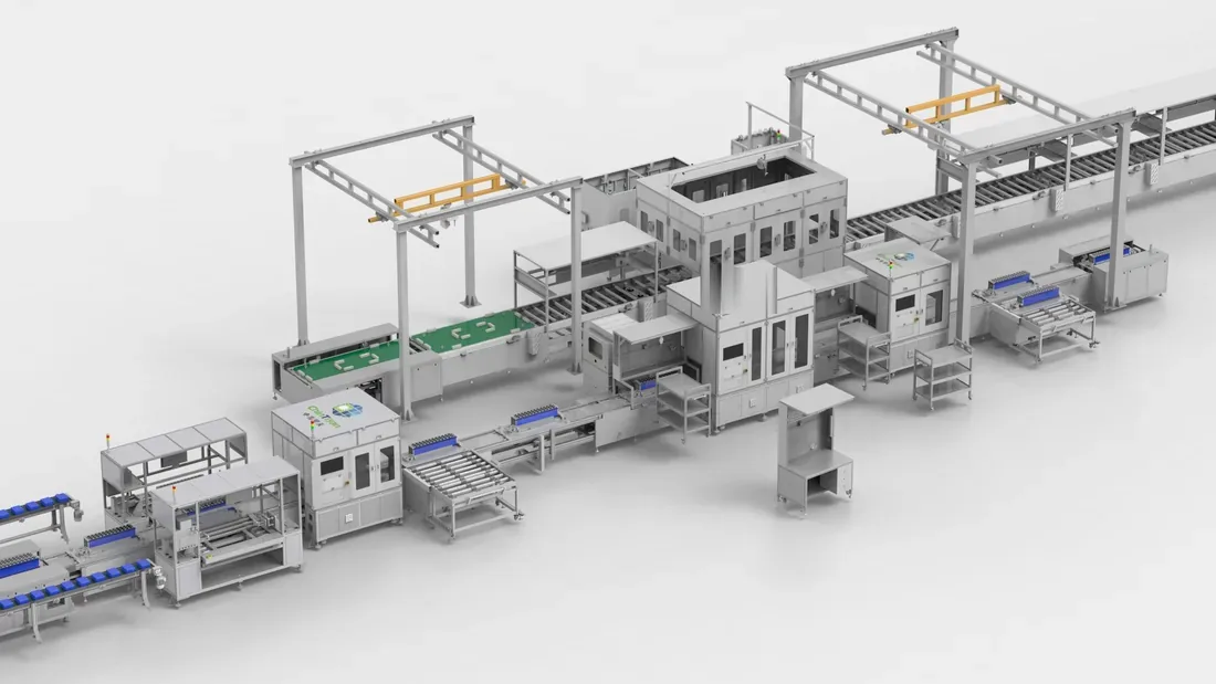

The economy line needs more compressed air than the standard one
3500 L/min against 3000. It is not a typo, it is not rounded, and it is the single strongest reason this page prints each configuration separately instead of printing a range.
- 01 · Why this one matters
Buyers do not read utility figures — they infer them
The reasonable assumption is that a more automated line draws more of everything, so the three configurations should line up 200 → 250 → 300 kW and 3000 → 3500 → 5500 L/min. Installed power does behave that way. Compressed air does not — and an assumption is exactly the kind of thing nobody checks, because nobody knows they made it. - 02 · What the wrong assumption costs
You size the compressor for the line you almost bought
Choose the economy configuration to save capital, size the air system from the standard build's 3000 L/min, and you are 500 L/min short. That shortfall does not appear on a drawing. It appears when every pneumatic station runs at once for the first time — which is commissioning day, on a floor that is already committed. - 03 · What we do about it
Each configuration gets its own cell, and the table has no ranges in it
3500 for the economy build, 3000 for the standard build, 5500 for the high-automation build. We do not publish "3000–5500 L/min" — that span is arithmetically true and operationally useless, because the number you need is one of three specific values and the range conceals which. - 04 · The evidence is the cells themselves
Read across the row, not across the dash
The same discipline applies to nitrogen: 20–40, 40 and 40–80 L/min. Two of those three are genuinely ranges — each for one configuration — and the third is a single value. Flattening all of it into "20–80 L/min" would be true, and would tell you nothing about the line on your order. - 05 · If you are between configurations
Ask, do not interpolate
If your project sits between the economy and standard builds, the compressed-air figure is not something to average — the two are not on a line. ⚠️ And to be straight about it: the source data states the three values and does not explain why the economy build sits above the standard one. We publish what we have and we are asking the plant for the reason; we are not inventing one to make the table look tidier.
This is the only figure on the page that behaves this way. The other four rise, stay flat, or are identical across all three configurations.
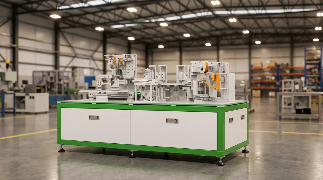
Take this to any supplier
"Is that compressed-air figure for the configuration I am buying, or is it a range across your whole product line?"
› — What a real answer contains
- One value, attached to one configuration
- The pressure it is quoted at, stated with it
- Whether it is peak or continuous demand
The one place a range is genuinely useful
Send three building numbers and we will say which configurations fit
Length, width and clear height to the lowest obstruction. That is enough to say which of the three fits your bay straight, which folds, and which does not go in at all.
Reply within 24 hours / If none of the three fits your building, we will say so in the first reply
Nitrogen at 0.5 MPa, and where it is actually consumed
The smallest of the four services and the one most often left off a utility schedule entirely, because it is the only one that is not obviously about moving something.
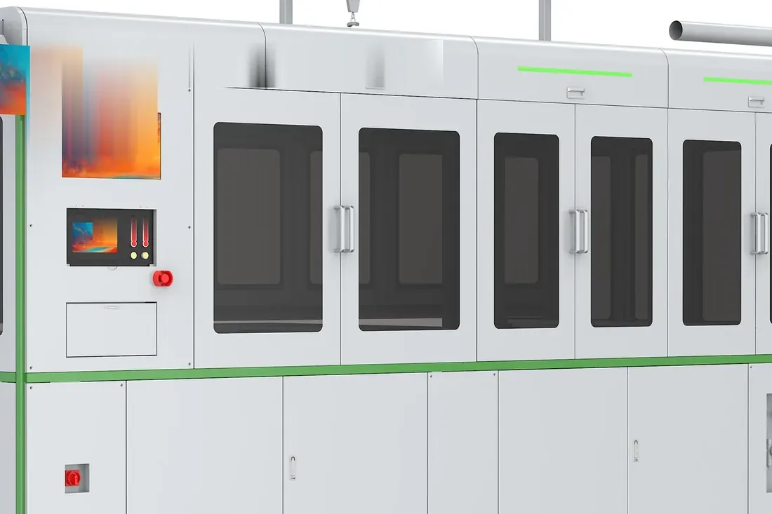
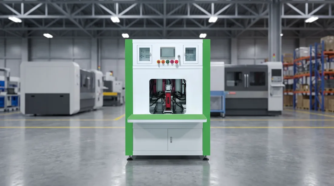
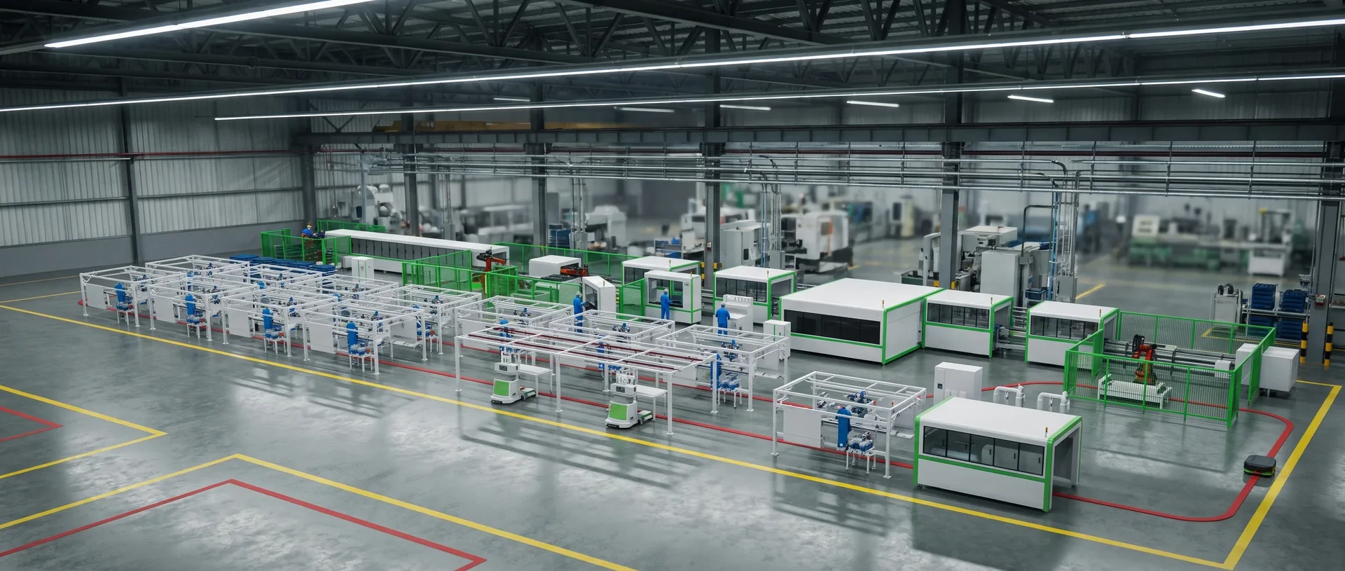
0.5 MPa for all three configurations
It is shielding gas, not utility air
Two of the three figures are ranges and one is a point
Supply form is yours
Nitrogen is the service most likely to be missing from a utility schedule somebody else drew, and the fastest to add — provided it is added before the line is commissioned rather than during.
One line for your utility schedule
"Nitrogen, 0.5 MPa, flow per the configuration on the order — supply form to be decided by us, delivered to the module segment."
Whether the line runs straight or folds back is a building answer
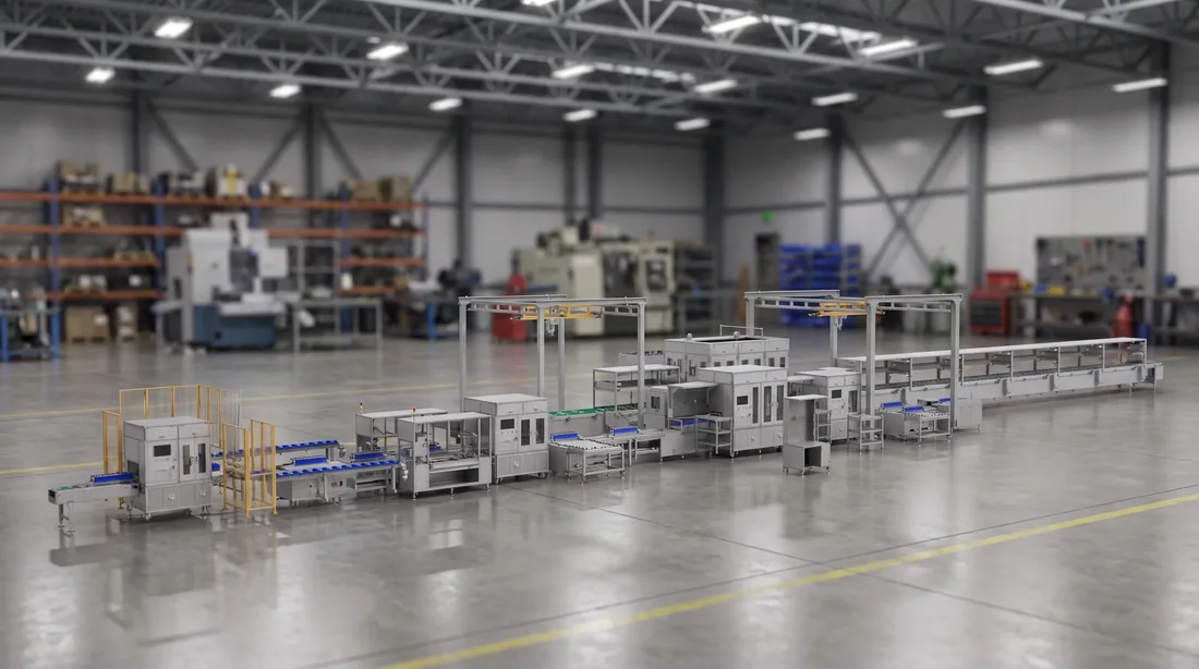
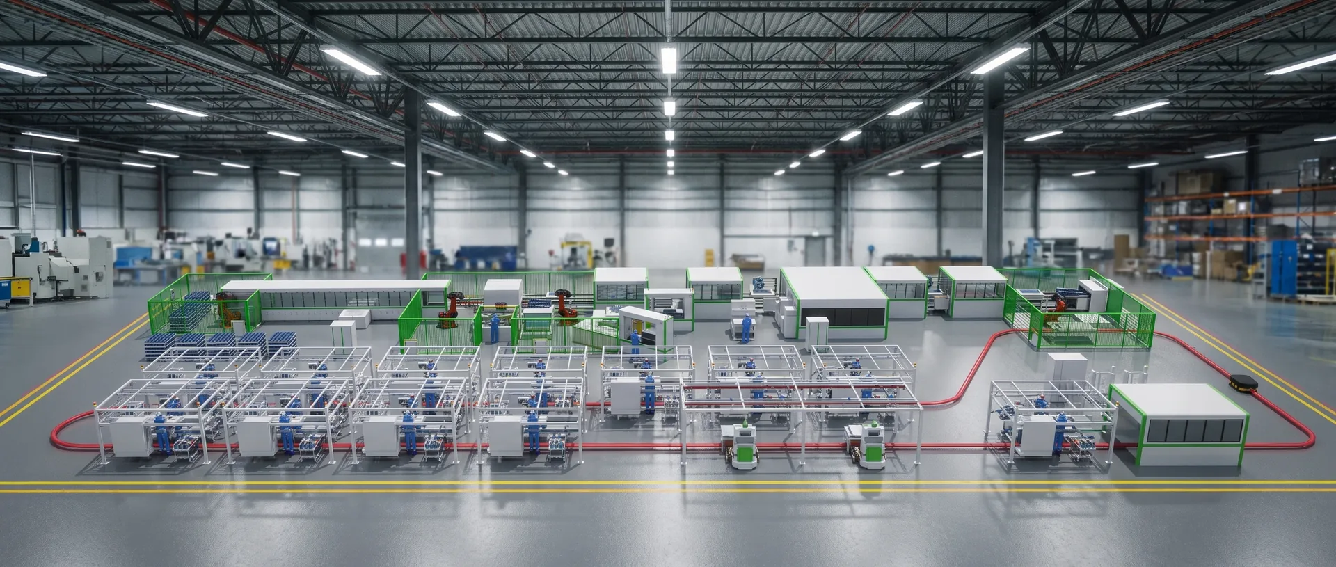
The three configurations are between 54 and 56 metres long and between 9 and 20 metres wide. Which of those two dimensions your bay is short of decides what the layout has to do about it.
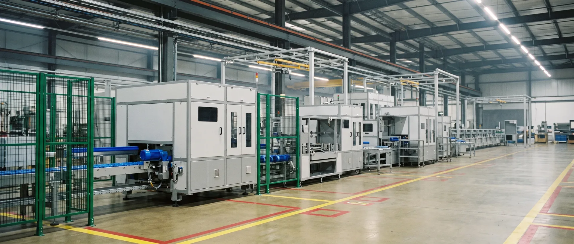
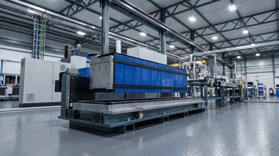
Every figure on this page, in one table
⚠️ Read across each row rather than down each column. Three of the five rows are identical across configurations; the two flow rows are not, and one of them runs backwards.
| Service | BLP-P8SSemi-automatic · economy | BLP-P8Standard | BLP-P15High automation |
|---|---|---|---|
| Electrical supply | Three-phase five-wire380 V ±5%, 50 Hz | Three-phase five-wire380 V ±5%, 50 Hz | Three-phase five-wire380 V ±5%, 50 Hz |
| Compressed air | 3500 L/min0.5–0.7 MPa | 3000 L/min0.5–0.7 MPa | 5500 L/min0.5–0.7 MPa |
| Nitrogen | 20–40 L/min0.5 MPa | 40 L/min0.5 MPa | 40–80 L/min0.5 MPa |
| Floor loading | ≥800 kg/m² | ≥800 kg/m² | ≥800 kg/m² |
| Clear height needed | 4 m | 3.5 m | 4 m |
How to use this table
"Take the column for the configuration on your quotation, and hand that one column to whoever sizes each service. Do not hand over the table."
› — Three rows are the same everywhere
- Supply form — identical across all three configurations
- Floor loading — identical across all three
- Air and nitrogen flow — different in every column, and one of them is not sorted
Six things a utility schedule needs that are not on this page
Naming them is more useful than a blank. Two are ours to answer once we know your project; four belong to somebody who is not us, and saying which is the point.
Ambient conditions and extraction
Not printed
Who answers it
Drainage, trenches and pits
Not printed
Who answers it
Lifting and installation access
Not printed
Who answers it
The two we will answer are ambient conditions once we know your adhesive, and access once we have your building drawing. The other four are answered by people who work in your building, and a supplier who filled them in from a template would be describing a factory that does not exist.
Four questions to put to any supplier before the building is committed
All four can be asked by email, none of them needs a drawing, and the answers are more revealing than the equipment list they arrive with.
"Are these figures per configuration, or one range?"
"Is the clear-height figure to the roof or to the lowest obstruction?"
"Five-wire or four?"
"What do you need from us, and by when?"
Our four answers are on this page: per configuration, in one table; to the lowest obstruction; five-wire; and all of it before commissioning rather than during.

Where the line figures and the acceptance sequence are written up
This page owns the building side, and nothing on the line side.
- Choose a configuration
- Building and utilities — you are here
- Acceptance
- Testing
Send the bay, and we will send back a layout in it
Length, width, clear height to the lowest obstruction, and anything already standing in the run. Four inputs, and the layout comes back drawn into your building.
What comes back
If the building will not take any of the three