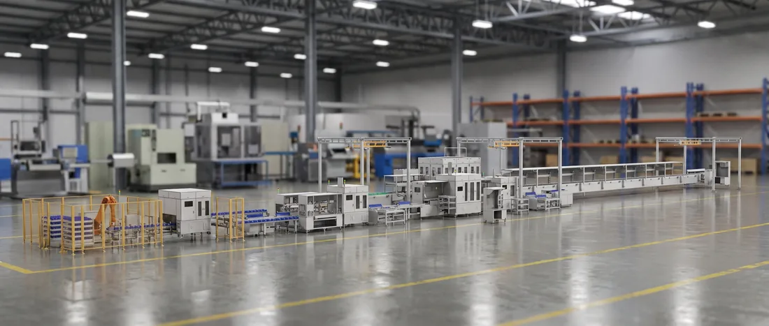
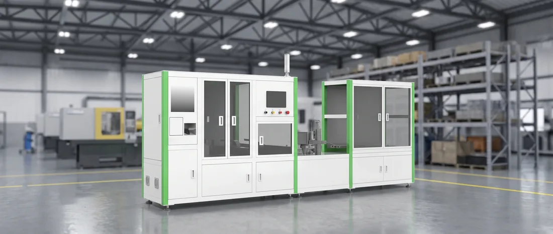
Cooling-plate and enclosure gluing / BLP-GL — pack segment, station 3 of 15
The Bead You Will Never See Again Gets Measured While It Is Laid
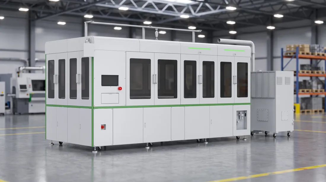
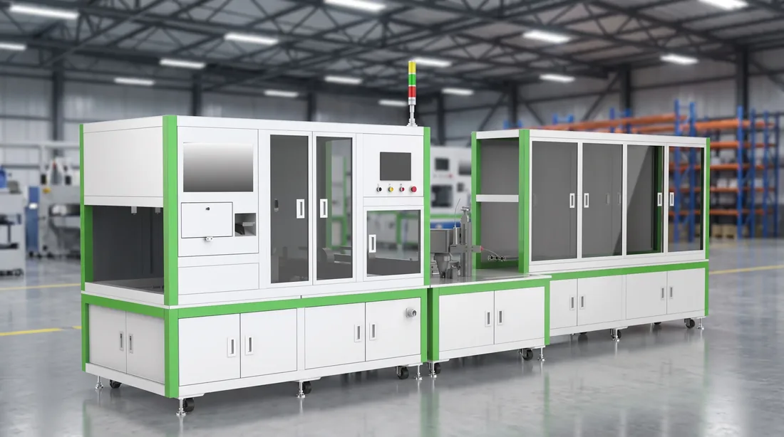
Once the modules go in, the adhesive under them is permanently out of reach. So this station is specified around evidence: ±0.2 mm vision positioning, a ±2 mm path, and dispensed volume held to 5%.
⚠️ ±0.2 mm and ±2 mm are not the same kind of number and are not in conflict. One is what the station knows; the other is what it promises. Section 07.
How this station makes evidence
- It looks before it dispenses — the bead lands on the part actually on the fixture
- It meters instead of estimating — volume is commanded, not judged by eye
- It records while it works — a pressure curve per bead, uploadable to your MES
- ±0.2 mmPhoto positioning
- ±2 mmDispensing path
- 5%Dispensed volume accuracy
- PROFINETParameters to MES
Station three of fifteen, and it works on two different parts
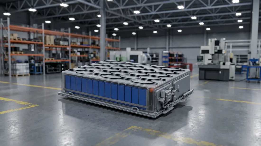
The pack segment starts with an empty enclosure and a cooling plate. Two stations later they are glued, and from the station after that nobody sees the adhesive again.
Pack segment · station 03 of 15 — enclosure floor and cooling-plate gluing

What comes in
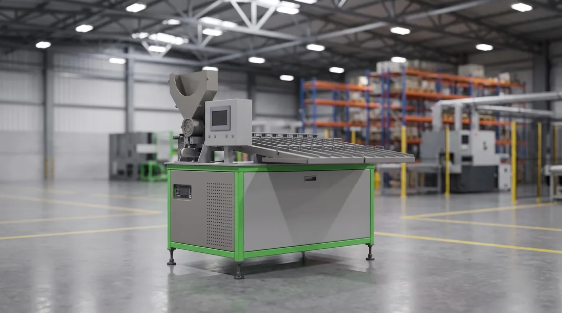
What happens here
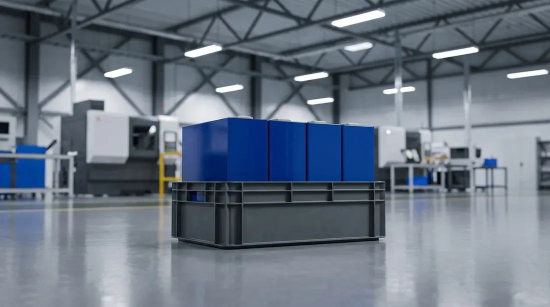
What closes over it
The reason this station is worth a page of its own is not that dispensing is difficult. It is that this is the last moment anybody can see the thing that has to be right — and a specification written for that moment looks different from one written for a machine.
What we build, and the point at which we stop
Adhesive dispensing is used in a dozen industries and most of the people searching for it are not building battery packs. One paragraph will sort that out.
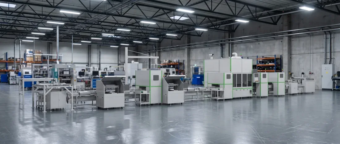
Every other station on this line makes something you can still look at afterwards. This one does not.
Position
Path
Volume
Four figures, and the question each one actually answers
⚠️ They are not four grades of the same accuracy. Each belongs to a different part of the job, and the commonest mistake is to compare them with each other.
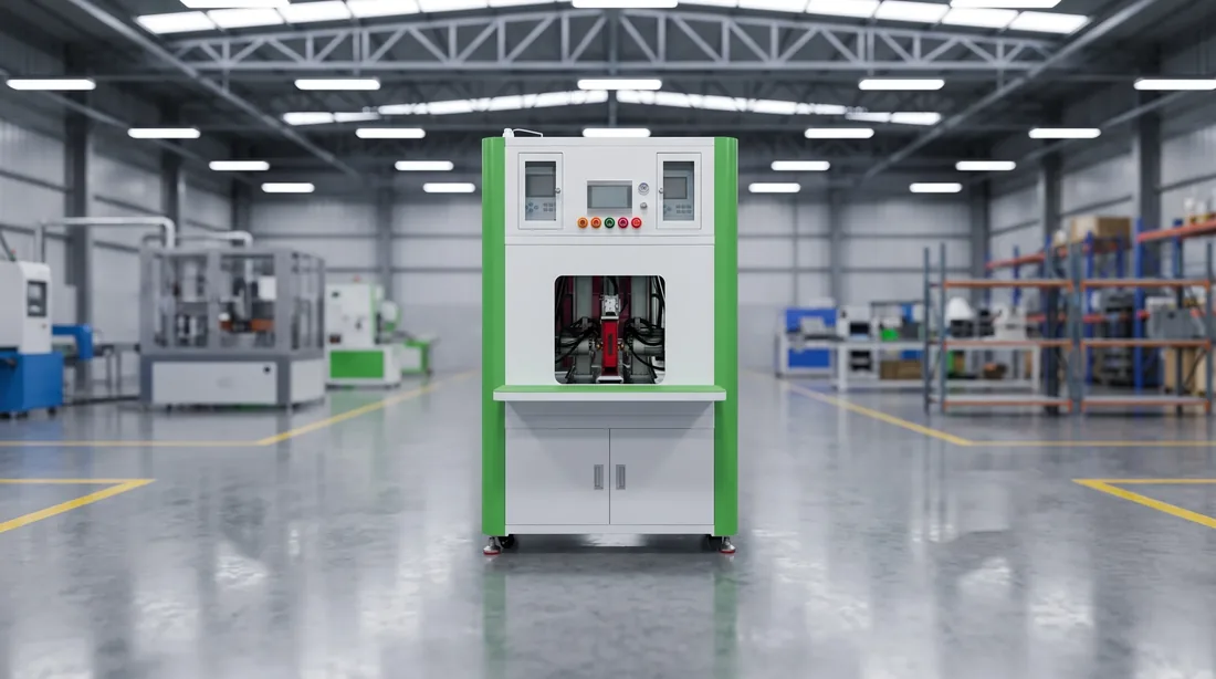
±0.2 mm · Photo positioning
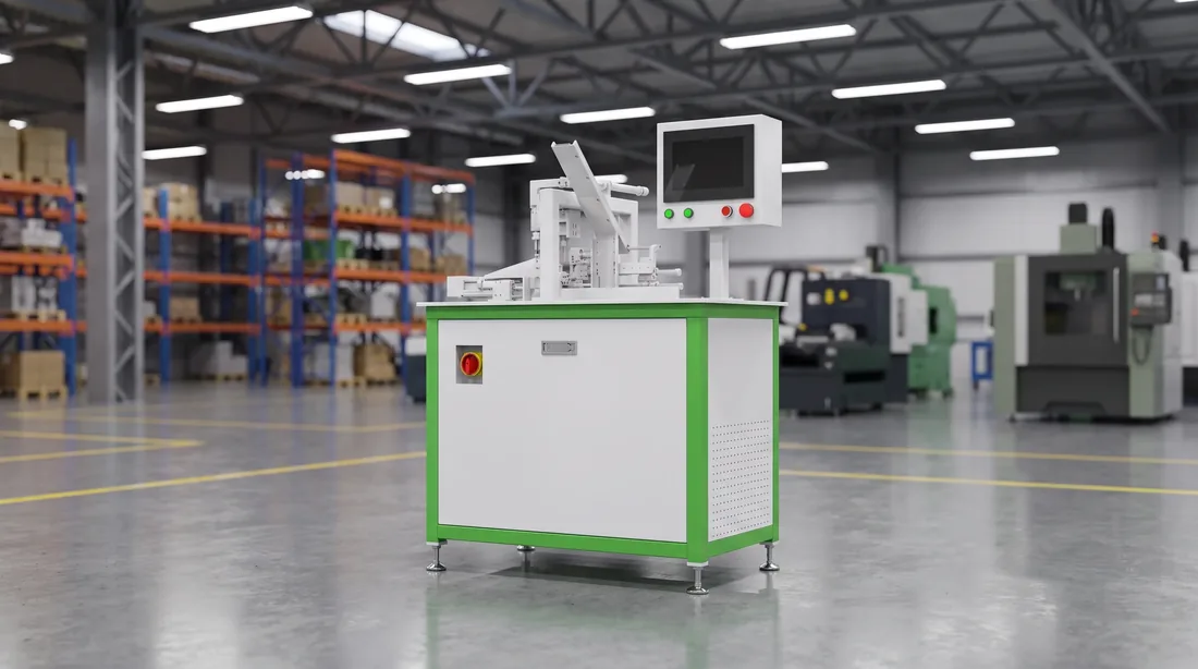
±2 mm · Dispensing path
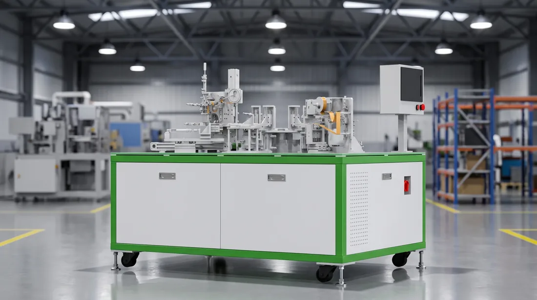
5% · Dispensed volume
PROFINET · Parameters to MES
Two of these describe geometry and two describe substance, and a specification that only argues geometry has argued the easy half. A bead in exactly the right place with the wrong amount of adhesive in it is a bead in exactly the right place. That is what section 06 is about.
Volume is what gets controlled, and pressure is what proves it
Twin-servo metering and a live pressure curve are one idea, not two features. This is the long answer, because everything this station can promise afterwards rests on it.
- 01 · Why volume, not appearance
A bead can look continuous and still be short
What a thermal-interface or sealing bead has to deliver is material in a place, and the eye is a poor instrument for material. Appearance tells you a bead was laid; it does not tell you how much of it there is, and the difference only shows up much later. - 02 · What a shortfall costs
The two ways it goes wrong are both invisible by station 4
A starved bead leaves the plate short of the contact it was designed for; an interrupted bead leaves a path where there should be a seal. Neither is visible once modules are in, and neither announces itself — which is why this is the one station on the segment where the process record is worth more than the inspection. - 03 · What twin-servo metering changes
Volume stops being a consequence and becomes an instruction
Two servo-driven metering axes deliver a commanded volume rather than a commanded pressure or a commanded time. Dispensed volume is then held to 5% against that command — and 5% is a figure about the material laid down, not about how fast the head moved or how an operator judged it. - 04 · What the pressure curve is for
It is the readable trace of an unreadable event
Pressure is recorded live while the bead is being laid, so a blockage, an air inclusion or a cartridge running out has a shape in the record. The curve does not replace the volume figure; it is what tells you which pack the volume figure stopped being true for. - 05 · When a curve looks wrong
It is a question about that pack, not about the batch
The value of a per-bead record is that it bounds the problem: this enclosure, this bead, this moment. Without it, one suspect pack at the far end of the segment puts every pack built that shift under suspicion — and that, rather than the adhesive, is what a bad day at this station actually costs.
How long a bad bead takes to report itself further down the pack segment is argued once, on the pack assembly line page, and is not repeated here.
Take this to any supplier
"Is your dispensing figure about the adhesive that left the nozzle, or about the pressure and the time you asked for?"
One number bounds the amount, the other bounds the blame
±0.2 mm and ±2 mm are answering two different questions
A ten-fold gap between two tolerances on the same datasheet looks like an inconsistency, and it is the thing we are asked about most. It is neither an error nor a compromise.
- Where is this enclosure, right now, on this fixture?
- Has the part shifted since the last one, and by how much?
- Should the path be drawn on the nominal part or the real one?
- Is the datum the station works from measured, or assumed?
- Where will the bead actually land relative to that located part?
- What is committed when your enclosure is at the edge of its own tolerance?
- How much room does your bead design need either side of nominal?
- What has to be true of the flange or channel for that to be enough?
Read them in order and they are one sentence: the station measures the part to ±0.2 mm so that a ±2 mm path is a promise about the bead rather than a hope about the fixture. A station that skips the measurement can still quote a path tolerance — it just cannot tell you what the tolerance is with respect to.
PROFINET gets the parameters out, and that is the point
A record that lives inside the machine is a record somebody has to go and fetch. Where this one is worth something is in the system you already run.
What is available
Why it matters more here than elsewhere
What we are not claiming
The honest version is short: the data is available and the plumbing is standard, and everything after that is a project decision. A supplier who tells you MES integration is included has either scoped it with you already or has not thought about it.
Send the enclosure drawing and the bead path you have in mind
Where the bead runs, on which face, and whether the same station has to do your cooling plate as well. That is enough to say what this station would be quoted as.
Reply within 24 hours / If a hand-dispensed bead is right for your volume, we will say so
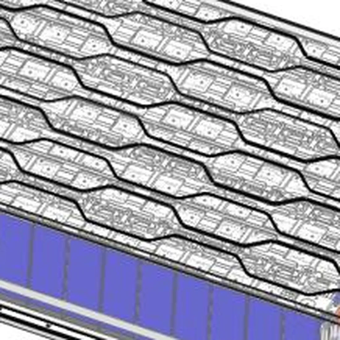
The cooling plate and the enclosure are not the same job
BLP-GL is specified for both, and reading that as "it does two things" misses what actually differs. Two of these cards are about the plate and two are about the box.
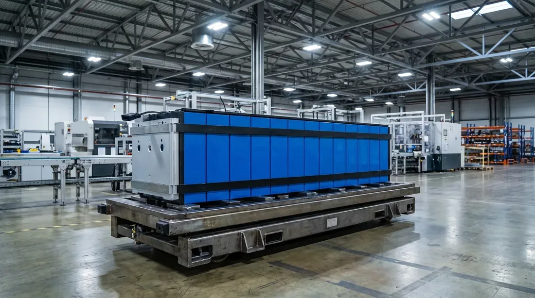
The plate · What the bead is for
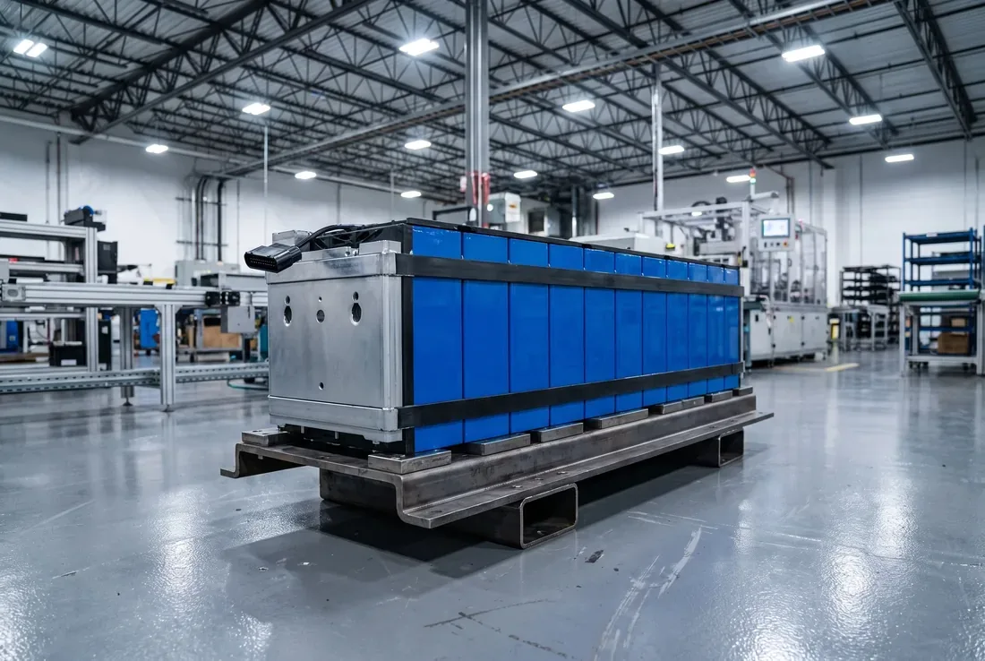
The plate · What makes it awkward
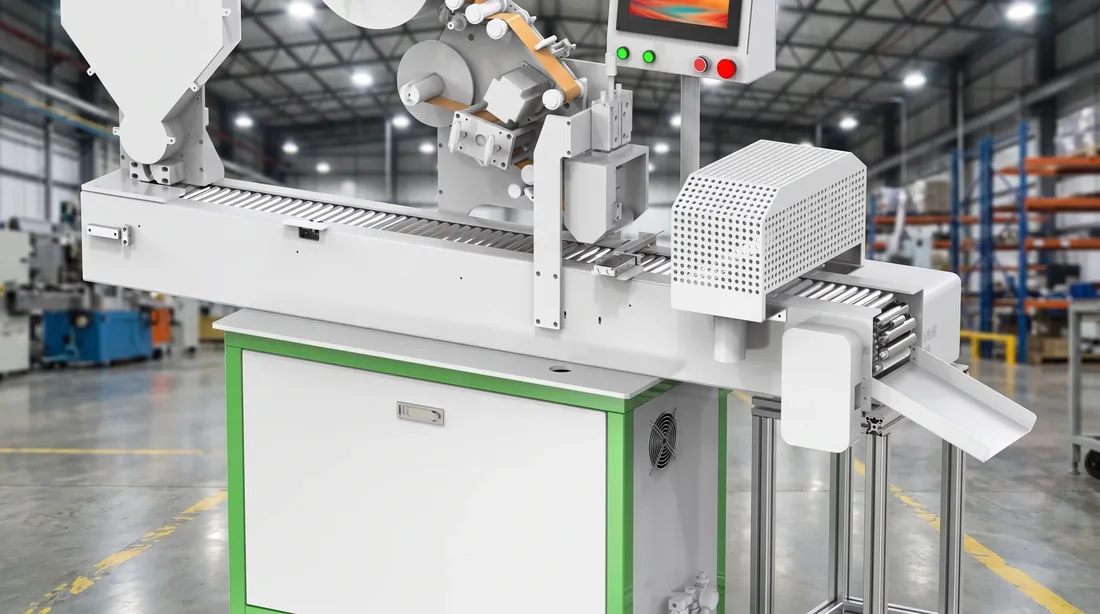
The box · What the bead is for
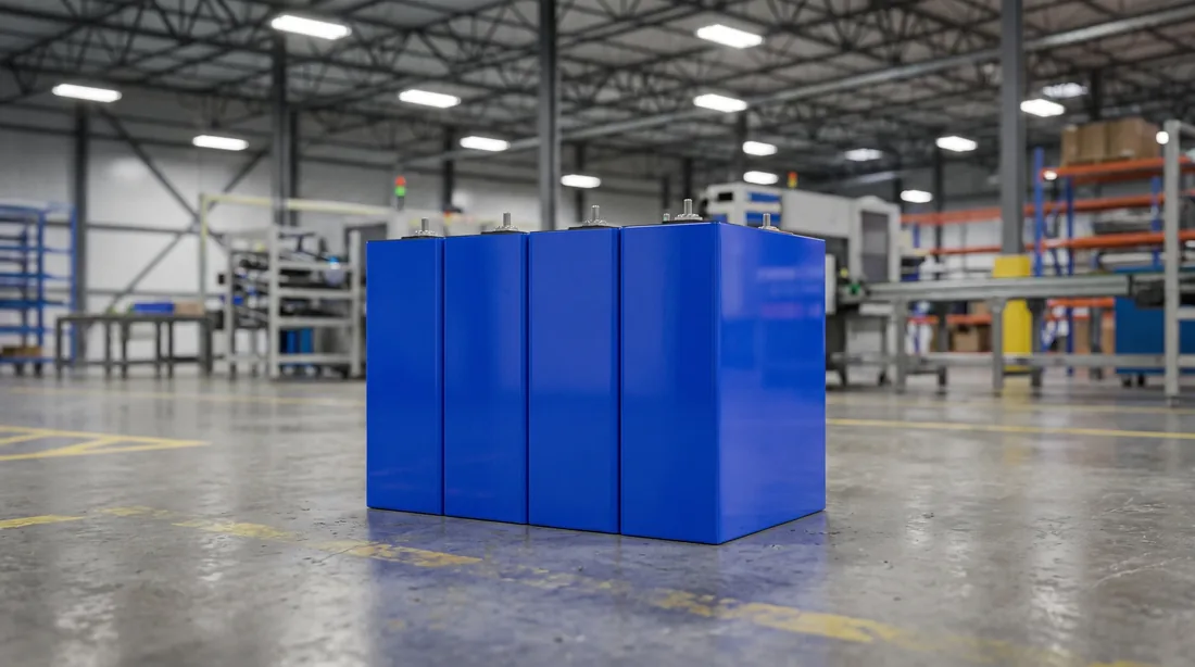
The box · What makes it awkward
One station, two workpieces, and the same four figures — but the figure that carries the argument changes with the part. On the plate it is volume; on the box it is continuity along a path. Anyone quoting you a gluing station should be able to say which one they optimised.
A new pack changes the path and the fixture, not the figures
This is the practical test of whether a dispensing station was engineered or configured, and it is worth putting into a quotation before anyone signs it.
- The bead path, taken from your new enclosure and plate drawings
- The fixture that presents the part to the camera and the head
- The commanded volume along that path, and the vision model of the part
- The commissioning samples that establish all three
- The ±0.2 mm positioning capability
- The ±2 mm path commitment
- The 5% dispensed-volume accuracy
- The record that goes out over PROFINET
The distinction matters because it tells you what a changeover actually costs. If a supplier's accuracy figures move when your part moves, they were never capability figures — they were a description of the last part that supplier ran. Within the compatibility envelope, a format change here is a path, a fixture and a re-commissioning. Compatibility and changeover →
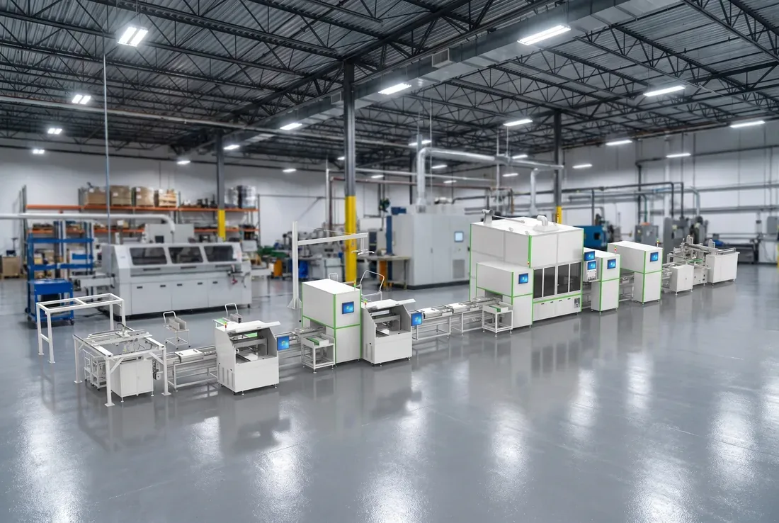
Four numbers you will want that are not on this page
Each blank has its own reason, and none of them is that we do not know. Naming them is more useful than filling them with a figure borrowed from another project.
The adhesive
Cure time
Grams per pack
Cycle time for this station alone
Two of these four are not ours to answer at all, and saying so is part of the specification rather than a gap in it. The other two arrive with your drawings — and asking for them before the drawings exist is how quotations end up describing a pack nobody is building.
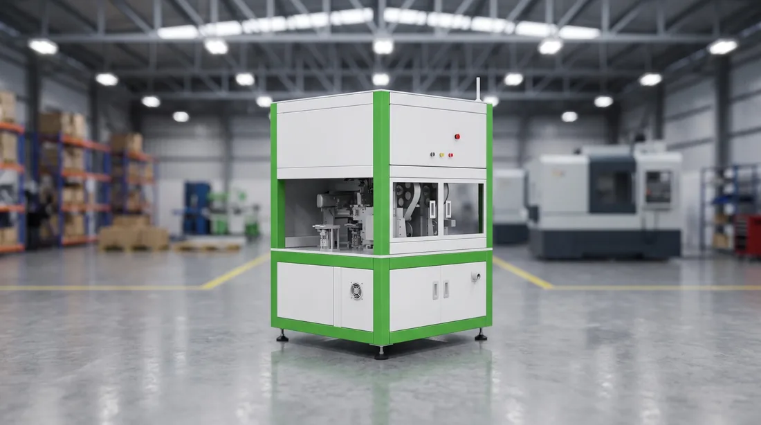
Five questions worth asking any supplier of this station
Including us. All five can be asked before a drawing changes hands, and the answers separate a dispensing station from a dispenser on a gantry.
Does the station measure the part, or assume it?
Is the volume figure about the command or about the material?
What evidence survives after the modules go in?
Where does the record go, and who maps it?
What changes if we switch adhesive?
Three things to look for in a dispensing line item
Shorter than the questions above and useful at a different moment: when you are holding two quotations and trying to see the difference.
Look for a measured datum
Look for volume, not pressure or time
Look for what leaves the station
Three checks, and none of them is about the machine's price. A dispensing station is one of the few line items where the cheap option and the expensive option produce a visually identical result — for about four stations, until the pack is closed.
Where the rest of the pack segment is written up
This page owns cooling-plate and enclosure gluing, and nothing else.
- Module segment
- Pack segment
- Gluing — you are here
- Testing and acceptance
Send two drawings and we will send back a scope
The enclosure, the cooling plate, and the bead path if you already have one. If you do not, say what the bead has to do and we will start there.
What comes back
If the answer is that you do not need this station